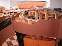
First up in photos is the fascia work at Wildcat canyon, just below Ophir. Rico is on the right, and the end of the Telluride peninsula is near the tissue box.
Here's a couple shots of the Durango yard, and engine terminal. Eli has found the turntable pit, as you can see!
Here's the siding at Dolores. This area is also serving at tool storage at the moment, so it's kinda messy. The peninsula with Telluride is on the left, and the line descending from Lizard Head on its way to Rico is on the right, above Dolores. As you can see, Eli has been busy with his toy cars, while the layout is out-of-operation during this phase of construction.
Here's the new wye at Vance Junction; Telluride is up a steep 4% grade beginning at the bottom of the photo. Vance proper is to the left, and the tunnels on the right lead to Ridgway. That's a little of Dolores on the far right, and the staging tracks at McPhee sneaking under the wye. The Christmas-tree lights are hanging from the line to Lizard Head (out-of-view in the upper right-hand corner). The lights are to help me see the McPhee staging once the scenery is in place, in case of derailments or whatever.
.
Here's the yard at Telluride, looking back toward Vance Jct. The high-line to Ophir is on the far left.
Here's a couple shots of the Ridgway yard. The wide tunnel in the first show leads to the staging tracks in the bathroom, and the mainline punches thru here on its way to Vance Jct. You can also see the beginnings of the engine termal at Ridgway tucked off on the left side.
In other news, I've run out of track (and money!), so further tracklaying will be on hold for a while. I've just started to work on the fascia at Durango, which is more difficult than the others because of tight clearances at the bottom. At locations like Rico, the bottom edge of the fascia pivots as it drops, because the hinge is a good ways above the bottom edge. This works because the benchwork framing is several inches back here. But at Durango, the benchwork is only about 1" back from the fascia, and there's no room at all for the bottom to pivot in. So, the hinge point needs to be at the very bottom of the fasica. I'm building extra bracing there to support the hinges at the right locations there, and know that I've figured out what to do, the work should be straight-forward (but we'll see!).
Oct 6, 2008
Sep 14, 2008
Two towns complete; back to wiring
I've continued to find time to lay track, and have laid all of the code 55 ME flex that I have. Ridgway yard is now complete (except for the engine terminal), and the wye at Vance Jct and all of Telluride is completed as well. All of the passing sidings are laid, and spurs are completed in Hesperus, Mancos, Ophir, and Vance Jct.
In the course of this, I changed the track plan of the Ridgway yard slightly (see updated drawings), moving the runaround track alongside the yard ladder, and adding two more classification tracks.
In laying Telluride, and 'test operating' it my head, I also realized that track plan needed changes. On paper, or in my Trainplayer design, I could switch the town by leaving parts of a train on the line coming into town, toward the wye. But in reality, I realized that stretch of track is on a steep 4% grade, so it can't be used for switching, and would make switching the town very challenging. So - I've added another runaround track, behind the depot (which is what the prototype did at most towns anyway). I lose a little real estate for buildings, but I thought this was really needed for (again) operational sanity.
And now that I'm out of track, it's back to wiring (since none of this new track is wired yet). A friend at work also convinced me it's time to get my block detectors installed. This isn't a signaled railroad by any means (the poor RGS hardly had the money for track, let alone signals). But, I'm designing this layout for operation, and with the hidden track I have I, some type of detection is necessary for operator sanity.
After a fairly long search, I've settled on BD8 detectors from The Signaling Solution. I plan to install one at Ridgway's panel (to handle hidden and staging tracks in that area) and another in Durango's wiring panel (to handle Durango staging, hidden tracks, and the hidden track under Rico).
Aug 18, 2008
Makin' more tracks
I've finally figured out (or think I have) how to lay ME's code 55 track. I've been going great guns the last couple weekends, and have laid all of the passing sidings (Rico, Hesperus, Ophir, Vance and Dolores), and have nearly completed the staging area and main yard at Ridgway.
None of this is wired yet, but it feels great to be making progress on track laying like this.
Jul 28, 2008
Off to Iowa this weekend
Well, this posting has nothing to do with trains. I didn't work on the layout at all, but instead spent Saturday with Vineyard's mercy response team in Cedar Rapids, Iowa, helping w/ flood-damaged houses there. I was really not expecting the level of damage this town has suffered - block after block of empty homes and deserted streets (except for the Salvation Army truck distributing food & water to folks gutting houses).
It was a good experience. Our national arm of our church - Vineyard USA - has set up a full-time operation in Cedar Rapids (modeled on it's continuing program in New Orleans), managing volunteer teams that go out and help families with flood-damaged homes. The water rose to 10' in many neighborhoods, and many of the homes being worked on were flooded to the top of the first floor.
We sent about 40 people out, but stayed only for Friday night and Saturday. My group of 6 gutted a house that hadn't been touched since the floods in mid-June, and it was RIPE! It was low-income rental managed by a Four Square church (whose building is also trashed). It was great old frame home, built around 1900, very large. It had been coverted into two apartments, and the lower one's family apparently just ran and left most of their stuff. It was pretty heart-breaking to drag out piles of clothes, toys, electronics, school backpacks still full of books, etc - a whole family's life of belongings, nearly. We pulled the belongings, appliances, and other stuff out, then ripped out the carpet, then started demoing the interior of the first floor down to the studs.
They tell me houses like this can be saved, and it would be nice - it's a great old place. But the damage was pretty bad.
Anyway - perhaps back to trains next week!
Jul 21, 2008
Still in fascia land...
I must admit I've been outdoors more these last few weeks, given the great weather, so the layout is languishing a bit. I did get some more work done this weekend - still working on fascia. I installed three more drop-down panels - two at Dolores, and one at Hesperus - although these will be secured with screws instead of magnets, as I don't intend to open them unless I'm working under the layout in those areas.
With these three completed, there's a only a couple small areas left now.
Jun 9, 2008
Fascia time
Shoot... has it really been three months since I posted here?
I (mostly) finished the 4 diesels I've been remotoring... decals are done, headlights are done, decoders are installed, and they are reassembled and operating. There's a few final delicate details (air brake hoses, cut levels, etc) that aren't added yet, and weathering isn't done, but other than that they're ready for the layout.
The layout, on the other hand, is back in the land of carpentry, as I've been adding fascia boards to most of the layout. I'm using untempered 1/8" masonite, and so far I've got about half of the layout done. There's a few sections that will have to wait, since wiring in the area isn't done yet (mostly around towns), but other areas are coming along.
Here's Ridgway - this is one of the areas where I've hinged the fascia, to allow access to the hidden track behind, and to make it easier to install controls into the fascia later:
And here's the area near the Enterprise branch:
And finally, a shot of the area near Ophir's bridge 45-A (to the right of this photo), showing the prep work for another piece being added. I'm using 1x2s on edge where I can, as something to either screw or glue the fascia to:
Apr 15, 2008
Still working on decoders!
I'm still working on those diesel rebuilds, but they're nearly done now. After figuring out that the headlight LEDs could be wired back-to-back, I'm on to the next phase. The LEDs look great; I've got one each for the upper / lower headlights, and only one comes on depending on which direction the loco is facing on the track. I ended up using 1.2k resistors, and the brightness looks about right to me. Track voltage w/ my Keller Onboard system is 14.5v DC. I mounted the LEDs by soldering a pair back-to-back w/ the right spacing (to match the headlights on the shell), filing the end of each LED flat, and super-gluing them to the rear of the headlight lens.
With the headlights done at last, I moved on to connecting the A- and B-units, installing the Keller decoders (called throttles actually) in the B-units, and routing some small stranded wires between the two units. On the F units, I mounted Kadee #47s (I think - short shank, underset, metal) couplers, and was able to run a wire thru each of the ear holes on the Kadee boxes. I used shrink-tubing to attach a second wire to each of these, and thus got four wires routed alongside the coupler boxes, looking almost like MU cables. Two wires carry motor power from the decoder in the B-unit, and two carry track power to the decoder.
What's left? Final details on the shells, and (probably later on ) weathering. Air brushing is another long-dormant skill, so I'll have to get back up to speed there as well. But with 4 new Keller-equipped locos, I'll probably focus next on getting Keller installed on the layout, so I can use these new guys.
I've also finally posted a newer version of the layout trackplan. I had created a design in Empire Express for another friend, and a fringe benefit of that is that I really learned how to dress up the drawing within that software package. What do you think?
Mar 31, 2008
Keller OnBoard and headlights
So, here I am, sitting at home and quietly finishing up super-detailing my 7 locomotive shells that I've been working on the past few weeks. Yesterday I finished up the last of the tiny decals I like to add - fuel & water labels, warnings, other little tidbits. I'm been using using diesel decals sets from Rail Graphics, purchased quite a few years ago - the last time I did this work, about 1991 believe it or not.
I also re-numbered one of the Athearn PA units (why must all PA-1 units out there be numbered 6009 !?), and finished up add numbers to the number boards of my Athearn PA and a pair of F7As. Not fun, but I did enjoy learning how to do it.
I suppose I should photograph these models when they're complete so you can see what I've been doing.
Anyway, back to Keller Onboard... I switch my focus to electronics, starting with the Lifelike Proto2000 PA / PB pair, which I thought would be the easiest. I had purchased a number of the 8-pin 2x4 NMRA plugs a while back, and soldered up just the track & motor connections on one of them, and plugged it into the NMRA plug on the PA to test it. The motor ran nicely w/ Keller, but no lights.
Of course - I hadn't jumpered the headlight connections. But, after some more experimenting, I found that the two headlight circuits are both polarity-sensitive (pins 6-7 for the oscillating headlight, and 3-7 for the lower headlight & numberboards). The oscillating headlight varies two circuits, to light two filaments inside one bulb to get the oscillating effect - about +/- 5v going to the bulb, but working on with pin 7 positive and 6 negative (I think - I might have it backwards). The lower headlight is just 1.5v, and again works w/ only one polarity.
With DCC, the decoder would provide the correct voltage and power to control these separately, and with normal DC both work but only when the locomotive's moving forward. The problem for me is that the rails will have a set DC polarity, regardless of which way the locomotive is moving. Thus, if the locomotive is on the rails facing west the headlights would work, but facing east they'd be off, regardless of whether it was moving or not.
I could replace both with my golden-white LEDs from NCE, and probably will I guess. I like the oscillating effect, but it uses the locomotives electronics and needs that certain polarity. I could light that bulb directly from track power (skip the electronics), and use a resistor to get down to 5v or so. No oscillating, but easier wiring. Or, I could replace both bulbs with the LEDs wired back-to-back, so that one LED would work for each direction the loco's facing.
I did finally figure out how to address the reverse-voltage problem... those LEDs don't like reverse voltage, and the Keller Onboard system puts 14.5v on the tracks. Turns out that with the LEDs back-to-back, one will light and the other won't, and the dark LED is protected from the reverse voltage by the current running thru the LED that does light. Assuming a current of 30 mA, I'll use a 3660 ohm resistor on one side of the two wires running to the LEDs. This is what I plan to use w/ the other locos.
What to do w/ the LifeLike unit? Not sure yet... I'm leaning now toward just lighting the two bulbs directly with appropriate resistors, if I can guess what their current draw is.
Mar 11, 2008
In a detailing mood...
I've been staying out of the basement lately, and have gotten into a super-detailing mood with some of my diesel locos. It started because I'd reached a point in layout construction where I wanted to install my command-control system (an old Keller OnBoard system). I've started working on that, but got to the point where I needed to install decoders (Keller calls them throttles) in some locos.
Not wanting to tackle the steamers yet, I figured I'd ease back into this by starting with some diesels (remember - my RGS is set in the late 1950s, and the SP has purchased rights or perhaps the entire road, so SP diesels will be showing up sometimes).
Keller likes low-amperage motors, and needs really great pickup in order to work smoothly. On my old layout, I'd converted a pair of GP35s and a pair of SW1200s, remotoring with Sagami can motors (I like the 2032 best), and wiring the units together in pairs, using all 4 trucks for pickups. I also replaced all the old Athearn wheels with NWSL wheels, again, for better pickup (the NWSL wheels are nickel-silver, and much better than the old style Athearn sintered iron or steel wheels).
Those engines will run great, and I next remotored my first Athearn loco, an F7 I received in the late 1970s I suppose. Then, I started on converting a pair of Athearn SP Daylight PA-1s. That project was put on hold about 14 years ago when kids came along, and have sat (in pieces) since then.
Fast-forward to today. I pulled out the ancient F7, and (for practice mostly) got that running again, It also has a Sagami 2032 can motor, hard wiring to both sides of the trucks, new wheels, etc. It needed a drive shaft repaired, and now runs like a top. With a little confidence now, I finished remotoring both PA-1s and two more F7-As, and installed new wheels and trucks on a pair of F7-Bs as well.
So now I'm ready to install the Keller throttles, right? Well, I also have a Proto2k PA-1 that's gorgeous, and really those Athearn shells could use some details. I'm going to use LEDs for the headlights, which means the shells will be hard-wired to the frames, which means any shell detailing is best done now.
Off I went to the hobby shop, and returned with MV lens, handrails, etc. I can't tell you how much fun it was to sit at the workbench installing lift rings, grab irons, and what not. It's been YEARS since I'd done anything like that, and it was very fun to return to. Plus, the basement is still cold and the workbench is upstairs in the comfy warm study. I'm sick of winter, and the warm study is inviting.
I'm still finishing up the super-detailing, and even added a backup light and cab room grabs to the Proto2k unit. I've got the LEDs ready, and will someday get the Keller throttles installed. That's gotta be last, because as soon as they're ready, I'll probably jump back down to the basement so I can get the Keller system installed, and then I might never return to the workbench and finish the detailing work!
Feb 11, 2008
Photos are here, and an update
I haven't posted many photos of late, but all the existing layout photos are still online - they're here in the blog. Just scroll down, and go to the older posts when you reach the end.
In other news, I've been monkeying around with the Keller OnBoard system, deciding exactly how to implement it. I have found that Keller produced a number of different versions of the throttles (decoders to you DCC folk), and mixers (power boosters). Here's some details of what I've discovered, in case anyone is interested:
The most recent mixer seems to have one huge heat sink, uses a red circuit board, and has options for digital components. Keller was one of a couple proposals for creating a digital command-control system (which eventually became DCC), but his design wasn't accepted. However, he did do a bunch of work creating a digital version of the OnBoard system, one that would work with both the analog and digital throttles at the same time. I'm not sure if he ever got that working, but looking at the extra space and layouts on the mixer, it was certainly in the planning stages.
Early mixers used blue circuit boards, the earliest having one heat sink, then versions with two heat sinks (still blue).
As to throttles (decoders), the T1 was eventually shrunken down to 0.7" long. The most recent version of it has an IC in a socket (as opposed to direct-solder), so between the size and the IC, I think I can now identify the most recent versions of the T1s. All of the smaller T1 versions also seemed to have better protection against overloads and overheating, and some type of H-bridge power output section. I have a number of T1s labeled both A and H, so I've been trying to figure out what the H meant; I think it referred to this newer output stage.
And finally, all of the newer T1s have a double row of solder points in the middle, so you could cut the unit in two (for tight fits), and run jumper wires between the 5 sets of solder points.
There was also a smaller T 1/2 throttle, but once Keller was able to shrink the T1, he discontinued the T 1/2 design.
Keller used 1/4" stereo jacks for his keypad plug-ins. I don't like those much, as they are kinda hard to remove and the strain is tough on the fascia and on the jack itself. I replaced all mine (on an older layout) with all-metal jacks, but the pulling is still not that great. Also, they short briefly when being inserted or removed, causing a warning beep from the mixer. I thought about using RJ45 connectors, as some DCC systems use, but those are kinda fragile.
I've settled on using 3-pin XLR jacks on this layout, the same as used for microphones (I do a bunch of theatre and concert lighting on the side, and we use a lot of XLRs). I haven't installed these yet, the jacks themselves are metal, they have a locking pin, and in genenral seem very robust. For the keypad, I'm using female black jacks, and for the layout / fascia I'm using male jacks.
I'll let you know how it works out.
Jan 28, 2008
1156 done at last
This weekend I finally finished installing the last of the 1156 lamps, covering all the blocks and other track sections on the layout. It's always a bit fussy soldering these lamps in place, so I'm glad to move on to something else now.
I've been running the layout's mainline a lot, now that it's complete. I've had the test train running forwards and backwards around the entire layout, at speed, and so far all looks good. I even reversed the loco / caboose so the engine was pushing the train from the other end, then ran that both forwards and backwards... still running ok.
Probably the next step is to begin working on the 'real' control system - my old Keller OnBoard. I've decided that I really need two 'mixers' (like DCC boosters), so I'll have to modify the main power bus a little to split it, and then build transition track sections (some gaps and a couple more 1156 lamps), as using multiple Keller mixers is a little different than using multiple DCC boosters.
Jan 14, 2008
More wiring at Ophir, and two accidents
A friend came over to see the layout this weekend, and ended up spending the entire day helping me wire the Ophir loop area. He spent most of his time working on a pair of 4-wire disconnects for the removable section, and wiring by safety rocker switch (which cuts power to both lines about 10' either side of the removable section). All that went very well, and most of the loop wiring is now complete. The panels at Vance Jct and Ophir still need the 1156 lamps installed, but then the basic wiring should be complete.
However, the weekend was marred by a minor derailment that dumped my two Bachmann Spectrum 2-8-0s on their sides. No damage - it was trivial derailment - but because I foolishly re-railed the double-header w/o turning off the power, the locos took off before I had the drawbar connected, and this stretched the loco / tender connector wiring. Now, one of those connectors is loose, and won't lock into position securely. It looks ok, but the loco stalls on turnouts where it never did before. I'm not sure how to fix it - perhaps just permanently wire the cab / tender together and bypass the little connectors?
And then - far worse - one of these same locos got knocked clean off the layout the following day; it landed on its side about 2' down on top of a plastic storage bin, which I guess cushioned the fall somewhat (certainly better than hitting the floor!). The tender's drawbar post snapped off, and the fitting on the drawbar screw under the cab also broke, let the cab / boiler pop up easily. I'm guessing I can install a new drawbar post on the tender, but I'm not sure what to do w/ the cab screw. It looks ok, but if you touch the cab it lifts off very easily.
Surprisingly, this appears to be the only damage! All the delicate pipes, steps, etc all seem fine.
Jan 7, 2008
Mainline is complete!
I reached a milestone yesterday - the mainline is now complete (well, except for the cutoff into Durango). It's not operational yet, as I've got some fine-tuning to do I suspect, and the wiring. But basically the rails over the entire Ophir loop, and both high-line and low-line, are complete.
I ended up using a #7.5 curved turnout for the Ophir spur, and the only one available was code 83. But, I found that using code 100 rail joiners worked very nicely to join the code 75 and code 83 rails. The oversize joiners are just sloppy enough to let the rails float a bit vertically, and it was trival to hold them in vertical position and solder them. I was actually kinda worried about this junction, but it turned out to be really simple and easy.
Jan 3, 2008
Progress over Christmas break
I had a few days off, and was able to (finally) push ahead with laying track up the Ophir high- and low-lines. That section is the last remaining portion of the mainline to lay, and it's now about half completed. Part of the delay was a lack of funds when I ran out of track, but I finally gathered up and sold a bunch of other stuff on eBay, and freed up some funds to continue.
I ran into another problem though, as I planned the spur at Ophir. The spur comes off the curving mainline just after the high bridge 45-A. I was planning to use a Peco code 75 turnout (as all my other turnouts are), but their only curved turnout has a very side outside radius (60" !!), and I just couldn't make that fit. So, plans now are to use a Walthers #7.5 curved turnout, which has radii of 32" and 28", and should be much more workable. It is code 83, so I'll have to figure out a conversion between the code 75 and 83 at this point; hopefully it won't be too bad.
For the code 75 to 55 transition (I want to use code 55 for sidings and spurs), I discovered that Micro Engineering actually makes a code 70 to 55 transition rail joiner, and I picked up a few. I haven't used them yet, but it looks like they'll work well.
Finally, a friend from an operating group south of Chicago dropped by for a visit, and we chatted about the operational possibilities fo the layout, once the trackwork is further along. I planned for operation from the beginning, but it was great to have someone else look at the layout and confirm that group operations would probably work well. I'm looking forward to that day!
Subscribe to:
Posts (Atom)